
| doi:10.3850/978-981-08-6218-3_SS-We023 |
 Final Paper PDF Final Paper PDF
|
NUMERICAL ANALYSIS OF ENDPLATE BEAM-TO-COLUMN JOINTS UNDER BENDING AND AXIAL FORCE
M. C. Rodrigues1,a, L. R. O. De Lima2,c, S. A. L. De Andrade1,b, P. C. G. Da S. Vellasco2,d and J. G. S. Da Silva3
1Civil Engineering Department, Pontifical Catholic University of Rio de Janeiro, PUC-RIO , Brazil.
amoniquecordeirorodrigues@gmail.com
bandrade@puc-rio.br
2Structural Engineering Department, State University of Rio de Janeiro, UERJ, Brazil.
clucianolima@uerj.br
dvellasco@eng.uerj.br
3Mechanical Engineering Department, State University of Rio de Janeiro, UERJ, Brazil.
jgss@eng.uerj.br
EXTENDED ABSTRACT
Steel beam-to-column joints are often subjected to a combination of bending and axial forces. Current specifications that take in account the steel semi-rigid joint behaviour do not consider the simultaneous presence of axial forces (tension and/or compression) acting in the joints. On the other hand, an empirical limitation of 5% of the beam plastic resistance is the only limitation suggested in Eurocode 3. In the cases where the axial force magnitude acting in the joint is less than this limit, its effects can be disregarded in the joint design. Despite this fact, the component method, proposed in the Eurocode 3, contemplate this situation since any component can be characterized, for any load type acting on the joint.
The component method, Eurocode 3 [1] consists of a simplified mechanical model composed of extensional springs and rigid links, whereby the joint is simulated by an appropriate choice of rigid and flexible components. These components represent a specific part of a joint that, dependent on the type of loading, make an identified contribution to one or more of its structural properties. The joint design must define three basic properties: bending moment resistant, Mj,Rd; initial rotational stiffness, Sj,ini and rotation capacity, ΦCd. The first step in a mechanical model development considering the component method for beam-to-column joints is the identification of the relevant components, which represent the existing deformation paths and possible ways of failure. The components are considered according to Eurocode 3 [1].
The main objective of this paper is to present a numerical study of a flush endplate beamcolumn joints. The investigated joints were initially subjected only to bending moment and later were under the combined actions of bending moment and axial forces. The numerical results were calibrated against experimental results and to the Eurocode 3 provisions.
The numerical model (see Figure 1) was based on tests carried out by Silva et al. [2], for flush endplate beam-to-column joints. The numerical simulation was performed with the finite element program ANSYS 11 package [4], using solid elements, SOLID 185, for the beam, column and bolts and shell elements, SHELL 181 for the transverse stiffeners adopted at the beam end near the load application point. In order to consider the contact between plates, contact elements TARGE 170 and CONTA 173, were used (endplate and column flange; bolt head and endplate; bolt shank and endplate hole and column flange; nut and column flange), with a 0.25 friction coefficient. A full nonlinear analysis was performed for the developed numerical model. The geometrical and material non-linearities were considered using a Updated Lagrangean formulation and a Von Mises yield criterion associated to a bilinear stress-strain relationship and an isotropic hardening response. This procedure represents the full structural assessment of the analysed bolted joints, and may be assessed and summarized using the stress distributions contour plots and/or force-displacement curves for any joint node [5].
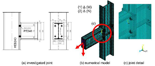
Figure 1: Flush endplate joint (series FE)
The present study investigated two cases: i) a model under the action of only bending moments and ii) a model considering the application of bending moments and a compressive axial force with a magnitude corresponding to 4% (52.7 kN) of the beam plastic capacity (1084 kN). The bending moments were applied at the beam bottom flange while the axial force was introduced at the beam cross-section area. Bolt pretension was also considered as acting on the bolt head and nut. The load was applied to the model in terms of an associated displacement.
A numerical and experimental results comparison indicated a good agreement in terms of bending moment resistance, initial stiffness and component yielding sequence. For the two studied cases, the presence of a compressive axial force in the joint led to an approximate 5% increase in the joint bending moment resistance, i.e., from MjRd=70,04kN.m to Mj,Rd=73,8kN.m for the joint FE01 [2] where only bending moments were applied to the joint. Future steps of this investigation will consider the modelling of additional cases subjected to other compression and tension axial force levels.
The authors gratefully acknowledge the Brazilian National and State Science Support Agencies: CAPES, CNPq and FAPERJ for the financial support granted to this research program.