
| doi:10.3850/978-981-08-6218-3_SS-We017 |
 Final Paper PDF Final Paper PDF
|
STRESS INTENSITY FACTORS FOR A WIDE RANGE OF LONG-DEEP CIRCUMFERENTIAL SEMI-ELLIPTICAL INTERNAL SURFACE CRACKS IN TUBULAR MEMBERS
Yang Yanga, Kun Pang Koub and Chi Chiu Lamc
Department of Civil and Environmental Engineering, University of Macau, Macau, China.
ama86532@umac.mo
bkpkou@umac.mo
cfstccl@umac.mo
EXTENDED ABSTRACT
Fatigue cracks usually propagate as surface cracks in stress fields in the direction of depth or length. In order to predict the crack growth rate and critical crack size, the changing stress intensity factor (SIF) along the crack front has to be prerequisite. Very often it may be sufficient to describe the surface crack as semi-ellipse with the axes a and c. In this paper, stress intensity factors for a wide range of long-deep circumferential semi-elliptical internal surface cracks in tubular members are presented. The crack configurations in the tubular members are subjected to axial tension loading and the SIFs are predicted by mean of 3-D finite element analysis. In this study, the SIFs were analyzed by considering the following three main parameters: (1) the crack depth to thickness ratio (a/T), (2) the outer radius to thickness ratio (R/T) and (3) the crack depth to crack length ratio (a/c). For a/T<0.8, current finite element results compared well with the results reported in literatures. However, the prediction proposed in literatures could not be applied to deep circumference surface elliptical crack with a/T>0.8. Therefore, finite element analysis was extended to investigate the SIFs by including a wider range of a/T ratio upto 0.99. Then neural network of MATLAB was used to process those finite element analysis results and suitable equations for predicting the SIFs were proposed. With the current proposed equations, the fatigue crack growth trend can be established which can help for estimating the inspection intervals for circular tube structures.
Key words: stress intensity factors, internal surface cracks, tubular members, finite element method.
1. Introduction
Tubular members have been used extensively in many engineering structures, such as offshore structures, and those members are not only subjected to static loading, but also cyclic loading such as wind loading and water waves. Therefore, the fatigue strength of those members is one of the major design concerns. Semi-elliptical shape cracks which are developed from initial flaws, are a common type of fatigue cracks found in the tubular members. In order to predict the fatigue life of such surface cracks, the calculation of stress intensity factors (SIFs) for surface cracks in tubular structures is essential. In the present study, finite element analysis was carried out to determine the SIFs for both shadow (a/T<0.8) and deep internal circumference surface elliptical crack (a/T>0.8).
2. Finite element analysis and results of SIFs
Finite element program, ABAQUS, is used in present study with the three-dimensional linear elastic finite-element models employed to calculate the SIFs by using quadratic brick elements C3D20 with 20 nodes and the elements around the crack tip were degenerated into crack tip elements. A typical finite element model of a tube with internal circumference surface elliptical crack is shown in Figure 1. Typical elastic modulus of steel (E = 210000 MPa) was assigned to the models. The analysis parameters included (i) crack deep ratio (a/T); (ii) crack length to circumference ratio (c/πR) and (iii) tube radius to thickness ratio (R/T) and the corresponding values are shown in Table. 1. The SIFs along the crack tip were obtained from FEA and were normalized with respect to the apply stress and crack length(Ft=K/√πa). Typical results of the normalized SIFs of the deepest point are shown in Figure 2 (a and b). It is shown in Figure 2a that the predictions according to Zahoor do not compare well with the FE results for small values of a/c (<0.2) and large values of a/T (>0.8). Therefore, the neural network of MATLAB was used to process these FE results of SIFs to obtain new set of equations and the corresponding comparison of the results are shown in Figure 2b. It is shown that the current predictions compare well with the FE results for a wider range of a/c and a/T values.
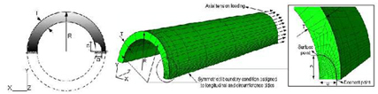
Figure 1: Typical finite element model and boundary conditions

Table 1: Parameters assigned in the finite element analysis
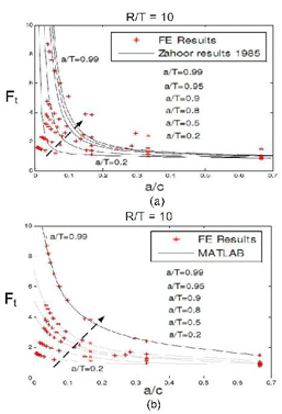
Figure 2: Comparison of FE results with (a) Zahoor’s prediction and (b) current proposed equations results