
| doi:10.3850/978-981-08-6218-3_SS-Th018 |
 Final Paper PDF Final Paper PDF
|
TOWARDS BETTER UNDERSTANDING OF A FRICTION CONNECTION IN TUBULAR FOR WIND TURBINES
M. Limam1,a, M. Veljkovic1,b, J. Naumes2,c and D. Pak2,d
1Div. of Structural Engineering, Luleå University of Technology, Luleå, Sweden.
amarouene.limam@ltu.se
bMilan.Veljkovic@ltu.se
2Institute for Steel Structures, RWTH Aachen University, Aachen, Germany.
cnaumes@stb.rwth-aachen.de
dpak@stb.rwth-aachen.de
EXTENDED ABSTRACT
The present assembling detail between two segments of the tubular tower segments used in to support wind turbines is accomplished by flange connection. This type of connection suffers from a rather low fatigue resistance class, in the range of 40 MPa. To remedy this drawback a new friction joint has been developed in the recently finished international RFCS research project HISTWIN (High-Strength Steel Tower for Wind Turbine). In order to study the behaviour of both type of joints, conventional ring-flange connections and friction connection, eight four point bending tests of down-scaled tubular tower section were performed. The behaviour of tests using the friction connection is described in this paper. A short summary of the experimental and numerical work, performed at RWTH and LTU, respectively, is presented in this paper.
1. INTRODUCTION
The main advantage of the new friction connection over conventional ring flange connections is the high fatigue safety of the joint. To guarantee for an easy assembling during erection High Strength Tension Bolts are pre assembled on the upper tower segment (incl. cover plates, washers and nuts), whereas long slotted open bolt holes in the shell of the lower tower segment allow the telescoping of both tower segments on site. In a final step the bolts are pre-loaded from inside the tower.
The test set-up of the experiments is shown in Figure 1. The main parameters of the specimens were monitored during the testing. The main objective of the experiments was to investigate behaviour of the connection and test feasibility of the assembling. The load-displacement curve and history of pretension force in bolts is well documented and discussed in the paper.
2. FE ANALYSIS
The numerical analysis is performed with ABAQUS. A very detailed 3D model was prepared where a very realistic model of the connection is achieved
The analysis is performed in three sequential steps: 2 pretension force steps and one step modelling bending of the specimen.
In the first step, an arbitrary small displacement of 0.3mm is applied in the head and the nut, until the gap between two segments of connection is reduced.
- In the second step the gap between two segments of the connection is closed introducing a pretension force of 160KN in all bolts, until the upper and the lower segments are in contact. In the paper, two different levels of the gap are considered: 2mm and 4mm which correspond to “manufacturing” tolerances of t/4 and t/2, respectively, where t is thickness of the cylinder.
- In the third step, a displacement is applied at the top of the specimen modelling the bending.
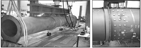
Figure 1: Test on friction connection performed at RWTH; test set-up and detail of friction connection
3. CONCLUSIONS FROM EXPERIMENTAL RESULTS AND FEA PREDICTION
The agreement between measured and computed load displacement curve is very good in a region that is used in discussion. The main conclusions are:
The reduction of stiffness of the specimen for the gap 4mm compare to the 2mm gap, obtained from FEA, at the level of the applied load about 1000kN is larger for the lower friction coefficient. The reduction is 10% and 20% for 0.5 and 0.7 of the friction coefficient, respectively.
Influence of a gap between inner and outer segments on longitudinal stress distribution along the shell is shown using results of the FEA.. The longitudinal stresses are closely distributed at the connection independently of the size of the gap. The holes with normal clearance are in the outer cylinder and the open slotted holes are in the inner cylinder, respectively. Therefore the outer cylinder is always more loaded because it is the stiffer part of the connection.
The force in bolts is necessary to close the initial gap dependents on the gap. The pretension forces of about 40kN, 50kN and 80kN are predicted as necessary to close the gap of 2mm, 4mm and 6mm, respectively.