
| doi:10.3850/978-981-08-6218-3_SS-Th005 |
 Final Paper PDF Final Paper PDF
|
KINEMATIC MODELS TO SIMULATE THE TORSION WARPING TRANSMISSION AT THIN-WALLED STEEL FRAME JOINTS
C. Basagliaa, D. Camotimb and N. Silvestrec
Department of Civil Engineering and Architecture, ICIST-IST, TU Lisbon, Portugal.
acbasaglia@civil.ist.utl.pt
bdcamotim@civil.ist.utl.pt
cnunos@civil.ist.utl.pt
EXTENDED ABSTRACT
The major difficulty associated with the analysis of the global three-dimensional behaviour of thinwalled frames by means beam finite elements stems from the need to handle the torsion warping restraint and transmission at the joints — the relevance of these effects depends on the (i) joint configuration, (ii) connected member orientations and (iii) cross-section shapes. Bearing this in mind, the authors have recently developed kinematic models to simulate the joint warping restraint and transmission in the context of frame structural analysis employing beam finite element formulations based on Generalised Beam Theory (GBT) — in particular, the work done dealt with torsion warping transmission at joints (i) connecting two or more non-aligned channel or I-section members (with flange or web continuity) and (ii) exhibiting configurations commonly used in building frames (unstiffened, diagonal-stiffend, box-stiffened and diagonal/box-stiffened joints).
The objectives of this work are (i) to provide an overview of the kinematic models mentioned above and (ii) to present and discuss numerical results concerning their incorporation into conventional standard 3D beam finite elements based on Vlasov’s theory intended to analyse the elastic global buckling behaviour of plane and space thin-walled steel frames built from channel or I-section members. In particular, one assesses how the joint configuration affects the frame critical buckling behaviour (buckling load and associated mode shape). For validation, most of the results obtained with beam finite elements are compared with “exact” values, yielded by shell finite element analyses - both the beam and shell finite element analyses (B-FEA and S-FEA) were performed in ANSYS.
In order to incorporate the torsion warping transmission kinematic models into structural analyses employing beam finite elements based on Vlasov’s theory, it is necessary to establish constraint conditions relating the torsion warping degrees of freedom (θ’— derivative of the torsional rotation θ) of the member (finite element) end section nodes that correspond to the frame joints. For that purpose, one must impose appropriate linear constraint equations — for instance, in the case of two connected members (finite element) one has

where (i) a and b are the end section finite nodes corresponding to the joint, and (ii) Ki are unit coefficients that vary with the warping transmission type, which in turn depend on the particular joint configuration. Figure 1 shows the characteristics and Ki values of four joint configurations (commonly used in building frames) connecting non-aligned channel or I-section members.
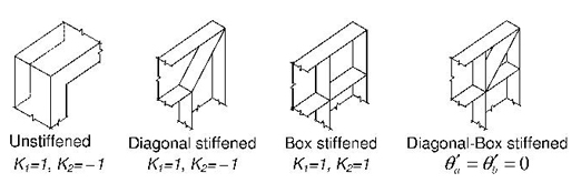
Figure 1: Joint configurations and Ki values
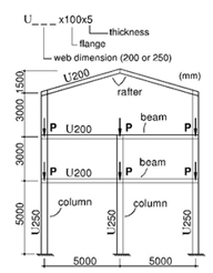
For the sake of illustration, one analyses the buckling behaviour of the symmetric plane frame shown in Figure 2, formed by plain channel members — the frame member in-plane behaviour involves major axis bending in all members. The column bases are fixed and the out-of-plane displacements are prevented (i) at all joints and (ii) at mid-height of all first storey columns (all these lateral supports are located at the cross-section centroids). Two joint configurations are considered, namely (i) box-stiffened column-beam and column-rafter joints, and (ii) a diagonal-stiffened rafterrafter joint. While the B-FEA was based on a frame discretisation into 1547 degrees of freedom, the S-FEA involved more than 33000 degrees of freedom. Figure 3 shows the frame critical buckling mode shapes yielded by the beam and shell finite element analyses. The observation and comparison of the two sets of frame buckling results prompt the following remarks:
(i) The frame critical buckling mode involves spatial (flexural-torsional) behaviours of all the members and, as it would be logical to anticipate, the instability is triggered by the first storey columns — indeed, the maximum displacements occur at the mid-height of those columns.
(ii) There is an excellent correlation between the buckling results yielded by the two finite element models. Indeed, there is a virtual coincidence between the frame critical (ii1) buckling loads (Pcr.BEAM=268.91 kN and Pcr.SHELL=265.97 kN − 1.1% difference) and (ii2) buckling mode shapes.
 |
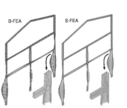 |
Figure 2: Symmetric plane frame |
Figure 3: B-FEA and S-FEA critical buckling mode shapes |
Finally, the paper showed that the inclusion of the developed kinematic models makes it possible to obtain very accurate frame global buckling results by means of B-FEA, which are computationally much more efficient than similarly accurate S-FEA (up to now the only rigorous numerical tool available) — this finding is bound to have far-reaching implications on the development of novel design and/or safety checking approaches for thin-walled steel frames.