
| doi:10.3850/978-981-08-6218-3_SS-Th004 |
 Final Paper PDF Final Paper PDF
|
EUROPEAN PROVISIONS FOR THE DESIGN OF WEB-TAPERED I-BEAMS — AN APPRAISAL OF THE EC3 “GENERAL METHOD”
A. Andrade1,a, P. Providência1,b, P. Borges Dinis2,c and D. Camotim2,d
1Department of Civil Engineering, University of Coimbra, Portugal.
aanisio@dec.uc.pt
bprovid@dec.uc.pt
2Department of Civil Engineering, Technical University of Lisbon, Portugal.
cdinis@civil.ist.utl.pt
ddcamotim@civil.ist.utl.pt
EXTENDED ABSTRACT
Tapered members are increasingly used in construction due to their unique ability to combine efficiency, economy and aesthetics — the three ideals of structural art. However, the advantages of tapering can only be fully exploited with an easy access to efficient analysis and design methods, leading to accurate estimates of the tapered member ultimate strength at a low computational cost. Some current steel design codes include provisions for design against lateral-torsional buckling (LTB) of laterally unsupported tapered beams under major axis bending. The so-called “general method for lateral and lateral-torsional buckling of structural components” in Eurocode 3 — Part 1–1 (EC3) is particularly attractive, since it covers arbitrary beam geometries, loadings and support conditions. However, its application to tapered members remains insufficiently documented.
In this work, the adequacy of the “general method” to predict the ultimate strength of doubly symmetric web-tapered I-beams is studied by comparing it with the results of geometrically and materially non-linear shell finite element analyses of imperfect beams carried out in ABAQUS. The scope of the study is summarised in Figure 1 — observe that the dimensions of the larger cross-section determine two distinct beam series, labelled A (“wide flange”) and B (“narrow flange”). In both series, the cross-sections may reach their plastic moments prior to the occurrence of local buckling.
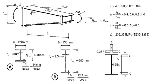
Figure 1: Web-tapered I-beams – Geometry, supports, loading and residual stresses
Figure 2 presents a graphical comparison between the “general method” and the ABAQUS results for the case α = hmin/hmax = 0.4. Each numerical simulation corresponds to a point in the plane  where λcr is the elastic LTB load factor, λpl is the load factor for which the plastic resistance is attained at the most unfavourable cross-section (not necessarily the smallest one), considering only the beam in-plane behaviour, and λu corresponds to the ultimate strength yielded by the ABAQUS non-linear analysis of the imperfect beam. These points are plotted in relation to the “general method” predictions, associated with the four buckling curves defined in EC3 section 6.3.2.2 (labelled a, b, c, d) and to Euler’s hyperbola. The observation of Figure 2 prompts the following remarks:
(i) The influence of the cross-section proportions is clearly visible. For a given end-moment ratio r, the points corresponding to series A (“wide flange”) lie above the series B ones (“narrow flange”). Moreover, the EC3 buckling curves c and d, applicable to welded beams with h/b<2 and h/b>2 , seem to be overly conservative. The numerical results indicate that the more favourable curves a (beam series A) and b (beam series B) would still be a safe choice.
(ii) In the low-to-intermediate normalised slenderness range, the numerical results indicate that it is worth exploiting the relation between the shape of the bending moment diagram MEd and the in-plane plastic moment envelope. A modification factor depending on MEd alone (like the f factor currently used in EC3 for “rolled sections or equivalent welded sections”) is not appropriate. Further studies are required before provisions can be defined that account for the relationship between the MEd and Mpl diagrams whilst preserving the simplicity and generality of the method.
The investigation is currently being extended to other beam typologies and loading conditions – the results will be reported in the near future.
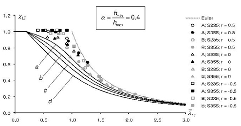
Figure 2: Comparison between the numerical simulations and the buckling curves in EC3 (α = hmin/hmax =0.4)