
| doi:10.3850/978-981-08-6218-3_SS-Fr007 |
 Final Paper PDF Final Paper PDF
|
CONSTRUCTION AND DESIGN OF UNDERGROUND STEEL TANKS IN SEISMIC AREAS: AN INTEGRATED STRUCTURAL AND GEOTECHNICAL APPROACH
G. Fabbrocinoa, G. Lanzano, A. Di Carluccio and F. Santucci De Magistris
University of Molise, Structural and Geotechnical Dynamics Lab, Department SAVA,
University of Molise, Termoli (Cb), Italy.
agiovanni.fabbrocino@unimol.it
EXTENDED ABSTRACT
The seismic behaviour of underground structures is generally satisfactory compared to the above-ground structure. However, in the recent strong seismic events some underground structure as tunnels, pipelines and tanks suffered high damage, despite of the buried structure confinement. A great effort is focused in order to evaluate the seismic vulnerability of these structure and to give codes instruments to the designers. Concerning the underground water and oil storage tanks, there are no indications on the seismic vulnerability of these structures in literature. Starting from the previous experiences in the seismic analysis of above ground industrial equipments and in the seismic analysis of the tunnels a research programme is in progress at the Structural and Geotechnical Dynamic Lab. StreGa of the University of Molise in field of underground industrial equipment. Concerning these structures, the dynamic response is strongly influenced by fluid-structure and structure-soil interactions.The damage observations are reviewed in order to identify critical issues of the soil/structure/fluid interaction during the seismic event. An introduction to the advanced numerical code LS-Dyna, able to perform reliable interaction analyses using real strong motion records, is given
METODOLOGY
Simplified numerical analyses were carried out using LS-Dyna: the numerical model is plane strain conditions, considering the cross section of the underground steel tank. The geometry of the model was built considering a single structure with circular cross section D=8.0 m and a steel lining s=0.03 m. The initial thickness of the soil layer, before the construction of the underground tank, is H=30 m and where the structure was positioned, is 39 m. Under the soil layers, a time history of horizontal accelerations was applied on rigid bedrock. The initial soil deposit had increasing value of shear wave velocity with depth, but a single value of damping ratio is considered. The simplified analyses were performed using a visco-elastic model for the soil and the structure. The input signal for the analyses was the acceleration time history of the very strong earthquake of Friuli (1976). Two analyses were performed: free-field analysis and soil/structure interaction. The numerical analyses of free-field model were compared to the results of one dimensional propagation performed by EERA.
RESULTS
The results of the analyses are showed (Figure 1) in terms of profiles of maximum acceleration and shear stress with depth. The comparison between the free-field analyses shows a good agreement between the analyses, especially in terms of acceleration. The two LS-Dyna analyses had similar values where the soil is far from the structure, which modified the response of the soil layer. The general effect of the underground is a strong increase of the showed parameters around the structure, which is amplified due to the low level of structure confinement
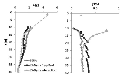
Figure 1: Profiles of a) maximum acceleration, b) shear strain
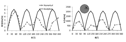
Figure 2: Maximum dynamic internal forces: numerical vs. Analytical.
For the interaction analyses the absolute value of the dynamic increments of the internal forces on the lining is also showed (Figure 2), compared with a closed-form solution. The comparison between numerical and analytical values of internal force showed a fair agreement: probably the difference between the calculations was due to the use of a high value of shear strain used in the closed-form solution. Next steps for numerical analyses will include the use of a more complex material model for soil, in order to take account of the cyclic degradation of the soil stiffness and damping, and the interaction with fluid inside the tank.