
| doi:10.3850/978-981-08-6218-3_CC-We016 |
 Final Paper PDF Final Paper PDF
|
NUMERICAL MODELLING AND PARAMETRIC STUDY OF BOLTED END-PLATE COMPOSITE BEAM-TO-COLUMN JOINTS UNDER UNBALANCED LOADING
A. Lachala and G. Loho
LGCGM, Structural Engineering Research Group, INSA, Rennes, France.
aAlain.Lachal@insa-rennes.fr
EXTENDED ABSTRACT
Bolted end-plate beam-to-column joints are currently used for the erection of steel and composite moment resisting frames. When these frames are subjected to static or seismic lateral loads, large unbalanced moments and consequently high shear deformations occur in the interior beam-to-column joints. In such conditions, these joints are most often semi-rigid and partial-strength and need to be strengthened to make them rigid and full-strength and so to satisfy some code requirements.
 |
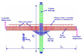 |
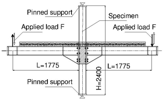
Figure 1: Bolted end-plate composite joint (tested specimen) |
Figure 2: FE numerical model, view of the mesh |
A research program has been developed at INSA-Rennes with the objective to study strengthening solutions for exterior and interior bolted end-plate beam-to-column joints. An experimental research program on steel and composite joints with both T and cruciform arrangement tested under symmetrical and unsymmetrical monotonic and cyclic loadings has been carried out followed by numerical studies. After a first F.E. three-dimensional model (presented at the Eurosteel 2008 conference) using cubic solid elements developed for welded beam-to-column joints, a more sophisticated three-dimensional F.E. model was developed for bolted end-plate composite joints including various strengthening solutions. This more recent model is presented in this paper with the main results compared to experimental data. In addition, a parametric study is carried out in order to analyse the influence of various parameter on the behaviour of such a joint and to determine the more efficient strengthening solutions.
The interior bolted end-plate beam-to-column joint under investigation in this paper is presented in Figure 1. It is one of the joint specimens of the experimental program fabricated and tested at the Laboratory GCGM of INSA-Rennes. The test setup is also shown in Figure 1. Figure 2 shows mesh details used for the FE modelling of the joint. The joint specimen presented in Figure 1 served as reference to develop the F.E. model. The modelling was developed using Castem2000 software.
The main characteristics of the F.E. discretization used to develop the numerical model presented in this paper are:
- 4-node thin shell elements with six degrees of freedom per node used to model the major part of the structural elements: beam, column, haunches, doubler-plates and transverse stiffeners;
- multi-layered thin shell elements used to model end-plates, column flanges and concrete slab in order to take into account the flexural behaviour of these parts of the joint;
- bar element to model the bolts connecting the end-plates and the column flanges;
- three-dimensional Timoshenko beam elements to model the shear studs.
Root radius and welds were also taken into account in the modelling.
Dealing with the material properties of the model, the structural steel is an elasto-plastic material governed by Von Mises yield surface including isotropic strain hardening. The behaviour of concrete is described using a Rankine fixed crack model for tension and an elasto-plastic law with Drucker-Prager criteria for compression. An uniaxial elasto-plastic law with linear kinematic stress hardening which associates the shear strain to the shear force is used for the beam elements employed to model the shear stud connectors. A bi-linear stress-strain relationship is adopted for the material behaviour of bolts.
Concerning the boundary conditions, the base and the top of the column are pinned. Symmetry boundary conditions are also applied to the relevant parts of the slab, beam and column. Unilateral conditions of support, characterised by the possibility of separation and contact, are used to model the contact between the slab and the column on the one hand, and between the column flanges and the end-plates on the other hand. It is assumed that the concrete slab cross-section and the steel beam cross-section have the same curvature and consequently no uplift occurs at the slab-steel beam interface.
The joint is loaded monotonically and subjected simultaneously to sagging and hogging bending (unbalanced moments). The loading is carried out by two monotonic vertical imposed displacements applied at each cantilever beam end with opposite directions (Figure 2).
A first comparison between experimental and numerical results shows a good agreement between numerical and experimental results as far as the maximum experimental moment is reached.
|
|
|
Figure 3: Plastic deformation of the column panel zone |
Figure 4: Plastic deformation of the joint (partially strengthened ) |
Figure 5: Plastic deformation of the joint (fully strengthened) |
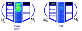
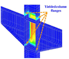
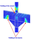
Other results such as elasto-plastic stress distributions and yielding evolutions in several parts of the joint: web panel (Figure 3), doubler plates (Figure 3), panel zone and column flanges (Figure 4), composite beams and column (Figure 5) are presented in order to give useful data for a better understanding of the behaviour of the joint.
Following these first results, a parametric study is undertaken in order to examine the influence of the following main parameters:
- the doubler-plate thickness effect on the stiffness and resistance of the column web panel,
- the column depth effect on the column web panel behaviour,
- the column flange thickness on the column web panel behaviour,
- the influence of the sagging/hogging bending moment ratio (transmitted by the beams to the column) on the moment-rotation behaviour of the joint,
The influence of the web panel distortion on the beam-to-column connection and consequently to the global moment-rotation behaviour of the joint was studied as well as the transfer mechanism of internal forces between the column and the concrete slab.
The conclusion underlines the interest of the main results of the numerical study to obtain useful data to develop more accurate analytical model and design method for the joints under investigation in this research.