
| doi:10.3850/978-981-08-6218-3_CC-We012 |
 Final Paper PDF Final Paper PDF
|
SEISMIC BEHAVIOUR OF STEEL TUBE-REINFORCED CONCRETE COMPOSITE WALLS
X. Jia, J. Qianb and Z. Jiangc
Department of Civil Engineering, Tsinghua University, Beijing, China.
ajixd@mail.tsinghua.edu.cn
bqianjr@mail.tsinghua.edu.cn
cjiang-z05@mails.tsinghua.edu.cn
EXTENDED ABSTRACT
This paper presents an innovative composite shear wall, named the steel tube-reinforced concrete (ST-RC) composite wall, which is a promising alternative to the conventional RC wall adopted in high-rise buildings. Steel tubes were suggested to be embedded at the boundary elements. The steel tubes and concrete cores act compositely as concrete-filled steel tubes (CFSTs), which offer the ST-RC wall a higher bending strength and a larger lateral deformation capacity. A series of quasi-static tests were carried out to examine the composite walls. The tested walls were designed with higher axial force ratios and relatively larger aspect ratios (over 2.0). The important properties of the walls were studied (i.e. the lateral load-carrying capacity, deformation capacity, and energy dissipation capacity). The effects of the steel tube/CFST ratio, axial force ratio, and transverse reinforcement at the boundary elements on these properties were investigated. The test results indicated that the ST-RC composite walls have both larger load-carrying and deformation capacities relative to the conventional RC walls. The ultimate drift ratios of the composite walls could achieve over 0.012. Based on observations from the tests and data analysis, some recommendations were proposed for seismic design of the ST-RC composite walls.
SUMMARY
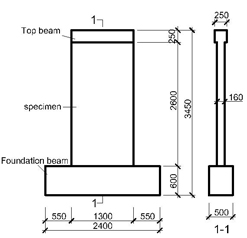
In this paper, an innovative shear wall called steel tube-reinforced concrete (ST-RC) composite wall is proposed by embedding circular steel tubes at the wall boundary elements. The steel tube and concrete core act compositely as a concrete-filled steel tube (CFST), which offer the ST-RC wall a higher bending strength and a larger lateral deformation capacity. To study the seismic behaviour of the ST-RC composite wall, seven walls labelled Specimens SW1 to SW7 were examined. Specimen SW1 was a conventional RC wall, and the others were ST-RC composite walls. The overall geometries of the tested walls are shown in Figure 1. All specimens had an aspect ratio (height-to-width ratio) of around 2.0, showing flexure-dominated behavior. Figure 2 shows the section dimensions, reinforcing details, and the confined boundary elements by shadowing. Three primary variables were considered in the tests: the steel tube ratio η (the ratio of the cross-sectional areas between the steel tube and boundary element), the design axial force ratio nd, and the stirrup characteristic value of the boundary elements λ. The variables for all test specimens are shown in Table 1. The specimens were classified into three pairs. Note that the design axial force ratios for the specimens were far greater than 0.5 (i.e., the limit value for the RC walls specified in Chinese seismic design code), and the stirrup characteristic value of boundary elements was no less than 0.2, which satisfied the Chinese design code provision.
 |
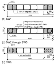 |
Figure 1: Elevation view of shear wall specimens (Unit: mm) |
Figure 2: Section dimensions and reinforcing details (Unit: mm) |
In the tests, a constant vertical load was applied to the specimen initially and then an increasing cyclic load was applied quasi-statically by the horizontal jack till a complete failure of the specimen due to concrete crushing developed at the wall bottom. Table 1 summarizes the load-carrying, deformation and energy dissipation capacities of the specimens, including yield load Vy and maximum load capacity Vp, yield displacement Δ y, ultimate displacement Δ u, ultimate drift ratio θu , and total energy dissipated by the specimens.
Table 1: Primary variables for specimens and test results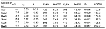
Key observations obtained from Table 1 are as follows: (1) The ST-RC walls showed a larger yield load, maximum load capacity, ultimate deformation capacity, and energy dissipation capacity relative to the conventional RC wall. The load-carrying, deformation, and energy dissipation capacities increased with the increase of the steel tube/CFST ratios. (2)The deformation and energy dissipation capacities decreased with an increase in the axial force ratio. (3) Under the design axial force ratio of 0.73 and the confined boundary element’s stirrup characteristic value of 0.20, the rectangular ST-RC wall had an ultimate drift ratio of 0.012, which was larger than the story drift limit (i.e., 1/120=0.0083 drift ratio) for RC wall structures specified in the Chinese seismic design code. Considering the reliability of the design, rectangular ST-RC walls that were adopted in severe earthquake-prone regions were suggested under a design axial force ratio no greater than 0.65 and a confined boundary element’s stirrup characteristic value no less than 0.2.