
| doi:10.3850/978-981-08-6218-3_CC-Th035 |
 Final Paper PDF Final Paper PDF
|
BUCKLING ANALYSIS OF COMPOSITE BEAMS WITH INTERLAYER SLIP
J. B. M. Sousa Jr.1, C. E. Oliveira1 and A. R. Da Silva2
1Department of Civil Engnrg., Universidade Federal de Ouro Preto, 35400000, Ouro Preto, MG, Brazil.
joao@em.ufop.br
2Department of Civil Engnrg., Universidade Federal de S. J. Del Rey, Ouro Branco, MG, Brazil.
amilton@metalicas.em.ufop.br
EXTENDED ABSTRACT
The purpose of this work is to develop and test a displacement-based finite element model for the nonlinear geometrical analysis of composite beam-columns with interlayer slip. The finite element is based on a total lagrangian description, in the context of large displacements, small strains and moderate rotations. The robustness and accuracy of the proposed scheme is verified against examples from the literature.
1. INTRODUCTION
It is common in structural engineering to employ members which consist of an assemblage of two or more different elements connected by a deformable interface. Examples are composite steel-concrete beams, where the connection is usually exerted by shear connectors welded to the steel beam and embedded in the concrete, and composite timber beams, glued or connected by mechanical devices. This is usually called interlayer slip, partial interaction or deformable connection.
The purpose of the present work is to develop a total lagrangian displacement-based finite element formulation for the nonlinear geometrical analysis of composite beam-columns with interlayer slip, which is able to handle nonlinear effects such as those present in composite steel-concrete beam-columns.
2. NUMERICAL FORMULATION
2.1. Displacements and strains
The kinematical hypotheses for the composite beam are based on the Euler-Bernoulli beam theory, namely, cross sections remain plane and normal to the reference axis after deformation. Second order effects are taken into account by the quadratic term of the transverse displacement derivative.
2.2. FE interpolation
To carry out the development of the FE formulation the displacement interpolation must be defined. For the axial displacements u0α (x) a and transverse displacements v the interpolation functions are introduced. The axial interpolation functions may be polynomials starting from the linear case. The transverse interpolation functions must reflect continuity of v and its first derivative, therefore they should be at least cubic (hermite polynomial).
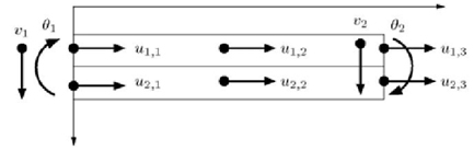
Figure 1: Finite element and degrees of freedom
3. NUMERICAL EXAMPLE
A two-layered beam with deformable connection is subjected to a compressive load P of 40 kN applied at different eccentricity levels of the lower member (Figure 3). The upper member has elastic modulus of 4.9 GPa and the lower member has an elastic modulus of 7.84 GPa. The connection stiffness is 49 MPa. The lack of symmetry of the structure produces small lateral displacements even for small values of the compressive load. Figure 4 shows the displaced configurations for the different eccentricities (11.25, 13.25 and 15 mm).
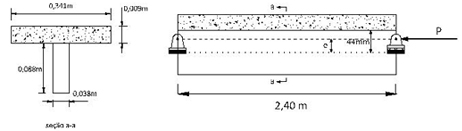
Figure 2: Nonlinear buckling example
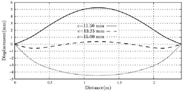
Figure 3: Displacement patterns for nonlinear buckling example