
| doi:10.3850/978-981-08-6218-3_CC-Th012 |
 Final Paper PDF Final Paper PDF
|
STUDY OF CONCRETE FILLED TUBULAR COLUMNS USING FINITE ELEMENT ANALYSIS
P. K. Gupta and P. Singh
Department of Civil Engineering, Indian Institute of Technology Roorkee, Roorkee, India.
spramod_3@yahoo.com
EXTENDED ABSTRACT
Structural members are generally made up of either steel or concrete or both steel and concrete as composite. The steel members show high tensile strength and ductility. On the other hand, concrete members have the advantages of high compressive strength and stiffness. If steelconcrete composite members are designed utilizing these structural properties of both virgin materials efficiently then the steel–concrete composite members exhibit the advantageous qualities of both materials, e.g., sufficient strength, ductility and stiffness. Concrete filled tube as a composite column subjected to axial compression demonstrates ideal combination of the steel and concrete.
In general, Concrete filled tubes commonly known as CFTs under axial compression have demonstrated enhanced load capacity, ductility and adequate energy absorption capacity. In CFTs, the steel tube serves as form for casting the concrete, which provides ease during construction alongwith reduction in construction cost. As such no other reinforcement is necessary, since the tube acts as longitudinal and lateral reinforcement for the concrete core. The improvement of structural properties of the CFT columns is mainly due to the composite action of steel hollow section and core concrete. The confinement provided by steel tube causes the core concrete to behave in a triaxial state of stress at the same time the core concrete prevents the inward buckling of wall of the steel tube. The distinct advantages of the CFT columns over the normal RCC and steel columns compelled the researchers to understand their behavior and load carrying mechanism. In recent past many studies have been carried out on CFTs columns but still the understanding of the behavior of CFT columns is insufficient. There is an enormous dissimilarity in the analytical models proposed by different codes and researchers for evaluating the strength of a CFT column and the effect of confinement.
In the present paper a study of the behavior of CFT columns using Finite Element analysis has been carried out. Commercial code ANSYS 11.0 has been used to model the CFT subjected to quasi-static axial loading. A three dimensional Finite Element model has been developed and used to develop the laboratory condition of testing of CFT columns in which a CFT column is held in vertical position between top and bottom parallel platens of universal testing machine. The top platen is moved gradually downward till failure of the CFT column. The computational results are compared with the experimental findings to validate the computational Finite Element model. After validation of computational model a parametric study has been carried out by changing geometrical dimensions of tube as well as grade of concrete. Steel tubes having outer diameter between 50 mm and 195 mm, wall thickness between 2.7 mm and 4.03 mm, length between 360 mm and 500 mm has been used. On the other hand concrete having 28 days compressive strength between 30 MPa and 55 MPa has been used. In some specimens, steel tubes were provided stiffener at their mid height to study its effect on load carrying capacity and ductility of CFT.
In this finite element model concrete core has been modelled using SOLID65 element and steel tube is modelled with SOLID45 element. To model interaction between concrete core surface and steel tube suitable contact has been defined. Both the elements are defined by eight nodes having three degrees of freedom at each node: translations in x, y, and z directions. The SOLID65 element is capable of cracking in tension and crushing in compression. The SOLID45 element has plasticity, creep, swelling, stress stiffening, large deflection, and large strain capabilities. The contact between concrete core and steel tube was defined as flexible to flexible using various options available in contact wizard. The surface of concrete core was defined as contact using CONTA174 element and steel tube surface was defined as target using TARGE170 element. The platens at top and bottom of concrete filled tube were defined as rigid target using TARGE170 element and top and bottom surface of concrete filled tube was defined as flexible contact using CONTA175 element.
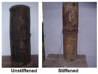
Figure 1: Typical mode of failure of unstiffened and stiffened concrete filled tubular column specimens.
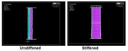
Figure 2: Typical Computed deformed shapes of unstiffened and stiffened concrete filled tubular column specimens.
It is found that the present finite element model is capable of capturing both local buckling and Euler buckling modes depending on the Length/Diameter ratio of tubes. The CFTs with Length/Diameter ratio more than 9 failed in Euler buckling where as less than 9 in local buckling in the form of multiple bulges. Figs. 1 and 2 show the true and the computed deformed shapes of stiffened and unstiffened both types of CFT columns. Both deformed shapes compare well. The variation of confinement has been predicted with studying the variation radial stress and it is found that the confinement is not uniform throughout the length of the CFT. It is also observed that confinement is not significant in the CFTs which failed in Euler buckling mode. The confinement of concrete is more when only concrete is loaded in a concrete filled tubular column. This is because when both concrete and steel tube is loaded, the steel tube deforms and hence allows the expansion of concrete under axial compression.
In case of concrete filled tubular column stiffened with horizontal stiffener, the buckling occurs above or below the location where stiffener is provided. The stiffener also increases the confinement of concrete core as it delays the buckling of steel tube. Since the mode of deformation changes with the provision of stiffener, so the peak load attained during compression process also changes i.e increases. This increase in the peak load is due to the decrease in effective length of column.