
| doi:10.3850/978-981-08-6218-3_CC-Fr016 |
 Final Paper PDF Final Paper PDF
|
BEHAVIOUR OF INTERIOR CFST COLUMN TO STEEL BEAM JOINTS WITH RC SLAB UNDER CYCLIC LOADING
W. Lia and L. H. Hanb
Department of Civil Engineering, Tsinghua University, Beijing, China.
awli02@mails.tsinghua.edu.cn
blhhan@tsinghua.edu.cn
EXTENDED ABSTRACT
The objective of this research is to investigate the cyclic behaviour of the joints consisted of circular concrete-filled steel tubular (CFST) columns and steel beams with reinforced concrete (RC) slabs. Four interior joints were tested under constant axial loads on the top of the CFST columns and cyclic loads at the ends of the beams. The main experimental parameters were the axial load level on the column and the section configuration of the beam. Then a finite element analysis (FEA) model for the composite joint under cyclic loading is presented. The feasibility of this FEA model is verified by the experimental results.
SUMMARY
It is known that the Concrete filled steel tubular (CFST) columns have being widely used in seismic regions for recent years. The CFST columns are often connected to steel beams in a real structural system, and the reinforced concrete (RC) floor slabs are usually attached to the steel beams with shear connectors. It is believed that, the steel beams with RC slabs exceed the plastic moment strength of the bare steel beams, which will result in a potential “strong beam-weak column” framing system, and the moment resistance capacity of the column will be changed (being stronger or weaker) due to the interaction of the compression and bending. That means the column will be “stronger” or “weaker” under larger axial load. Therefore it is of great importance to investigate the behaviour of composite joint with RC slab under large column axial load level.
In this paper, four 1/2 scale CFST column to steel beam with RC slab interior joints were tested under cyclic loading. The same profiles of steel tubes (φ219 mm×4.68 mm), width and thickness of RC slabs (700 mm and 50 mm) and size of external diaphragms (70 mm×5.62 mm) are applied for all specimens in the experiment. The RC slab and steel beam were connected together with shear studs under full shear connection criteria. Fig.1 shows the configurations and test setup of specimens. The axial load level (n) are between 0.33-0.66.
A finite element model using program ABAQUS was also introduced to simulate the joint behaviour. In the finite element analysis (FEA) of CFST joint, the steel and concrete components are simulated with separated shells and solid elements, respectively. They are assembled together by certain connection elements to form a joint assemblage. Four-node conventional shell element with reduced integration is used for steel tubes and beams in the ABAQUS software. Three-dimensional eight-node solid element with reduced integration is applied in modelling the concrete component. Three dimensional Timoshenko beam element with linear interpolation is used for steel rebars in the RC slab.
The measured load-displacement (P-∆) hysteretic loops obtained from both the test and calculation are present in Figs.2(1)-(4). The failure modes of the specimens are compared in Figs.2(5),(6). It can be found that the cyclic responses can be simulated by the FEA model well. Within the parameters of the test, it was shown that the axial load level had a moderate effect on the ultimate moment capacity of the joint. The ultimate moment under sagging and hogging moment both decreased when column failure occurred. The average ductile coefficient of the joint was about 3.7 for the specimens, which indicated that these joints had favourable ductile behaviours under a high level of axial load. It can be found from the FEA results that, the proposed modelling method provided generally good results, and this finite element model has a good prospect to be applied in further research.
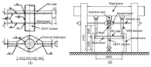
Figure 1: Test setup and specimen configuration (unit: mm)
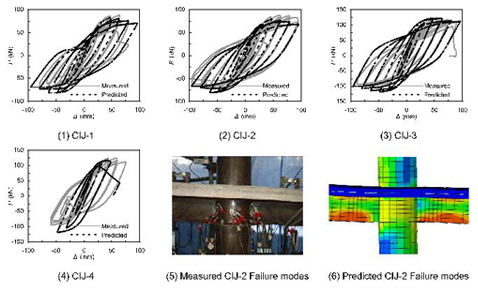
Figure 2: Measured and predicted hysteretic curves